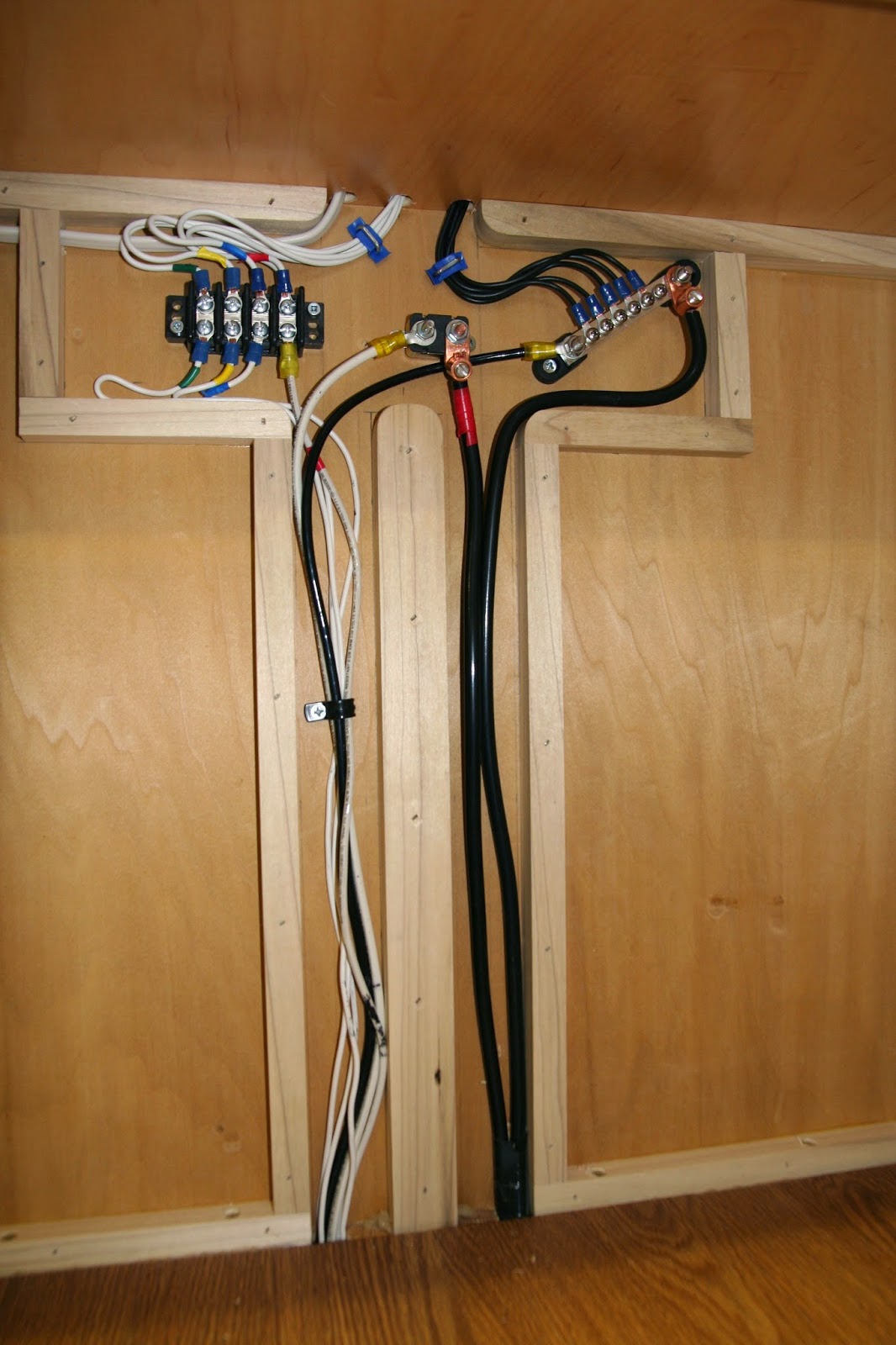
The diagram above shows the wiring plan for all of the electrics forward of the rear bulkhead which houses the inverter/ charger/ fuse box. There will be a second part to the wiring scheme that will feed the galley and exterior lights. The reason for breaking it up this way is that everything to the front of the rear bulkhead needs to be fed by wires that are buried in the floor. The wires for the rear half will be routed through the galley cabinets. The picture below shows the interior of the forward bulkhead all wired up. The top section is the junction box that is depicted by the large center box in the diagram. The cables coming up on the right come from the battery that will be mounted on the trailer tongue. The wires coming up the left side run under the floor and back to the main box.
 |
| These circuits will supply power to a pair of 12v outlets, a reading light, a dome light, a ventilation fan, and a 120v outlet. |
In the picture above you can see the back of the forward overhead cabinet. The picture below shows the front of the center panel of the same cabinet. The wires that you can see going through and into the roof section will feed the roof vent fan and overhead dome light.
The picture above shows the front of the magical electricity box that changes the currents into the right kind and keeps them organized and separated so they do not argue. It also keeps an eye on the battery charging so that it stays sort of Goldilocks. I apologize if I am being too technical for some readers here, but it can be difficult to discuss matters of electrical circuitry in lay terms. Below is the back of said magic box where all of the connections are made. It is pretty difficult to see in the photo, but coming through the side wall is the 120 AC inlet and coming up through the floor, just behind the rear bulkhead, are the DC bundle and the AC line that run under the floor to the front of the camper. The front opens into the sleeping compartment at the sleeper's feet, and the back is accessible inside the lower galley cabinet.
After all the connections were made it was time to see if it works. The picture above shows the 120 AC power inlet. We plugged it in, Sam did a few checky-type things with his volty-meter on the main breakers, we flipped the switch, and, as you can see in the picture below, the light came on. WooHoo! I played it of cool, but I was pretty psyched. We tested the 120 and 12 volt outlets and all were good. Next we pulled the battery out of my truck, hooked it up to the leads with jumper cables, and repeated the test; everything worked perfectly.
Now that everything that can be installed to this point is in, tested, and working, there are just a couple more things to do to bring this step to a close.
 |
| Foam insulation is cut to fit into the voids in the front bulkhead and glued in place. |
 |
| Next, 1/4" maple plywood finishes off the cabin interior. |
I've had these electrical components kicking around in my shop for so long now that it is a bit surprising to see them take their rightful places. I think part of the surprise is due to the fact that all of this is still, albeit a bit less, something of a mystery to me. I cannot thank Sam enough for taking the time to walk me through this particular aspect of the build. We have been talking a bit about some solar panels, maybe an inverter for the truck, so future episodes of "The Electrical Engineer" may be in the cards.


you go guys. very cool.
ReplyDeleteWish I coulda been there. I woulda contributed...to the beer consumption. Pop
ReplyDeleteRyan - Great work as always. Look forward to seeing and hearing more about the journey! Thanks for allowing us to come along for the ride...the boyz pass along their hellos to the gals up north...be well - jason
ReplyDelete